
No products in the cart.
This tiny breakout board for TI’s DRV8835 dual motor driver can deliver 1.2 A per channel continuously (1.5 A peak) to a pair of DC motors, and it supports two possible control interfaces for added flexibility of use: IN/IN and PHASE/ENABLE.
$6.79 CAD
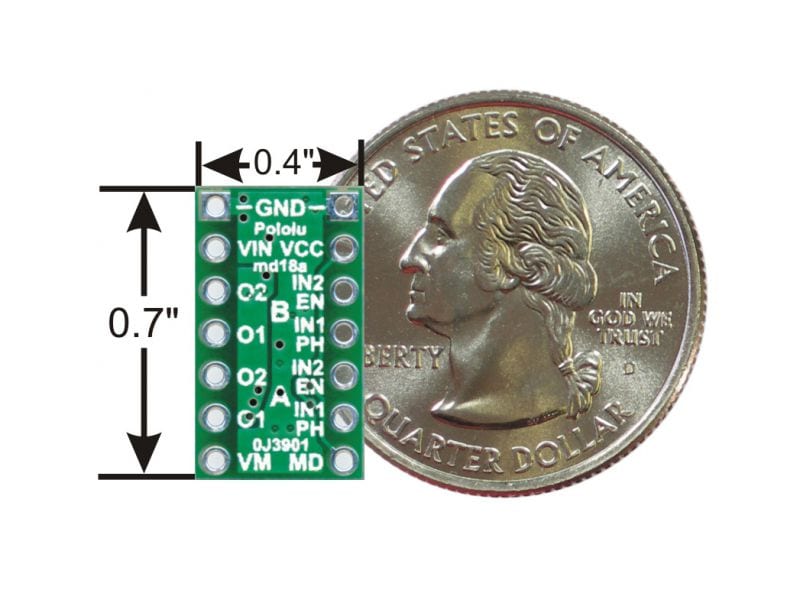
With an operating voltage range from 0 V to 11 V and built-in protection against reverse-voltage, under-voltage, over-current, and over-temperature, this driver is a great solution for powering up to two small, low-voltage motors. The carrier board has the form factor of a 14-pin DIP package, which makes it easy to use with standard solderless breadboards and 0.1″ perfboards.
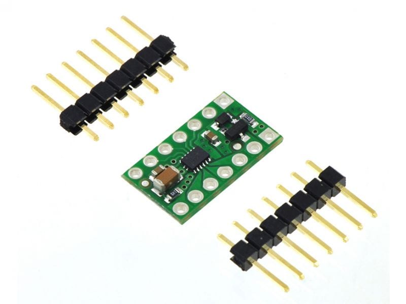
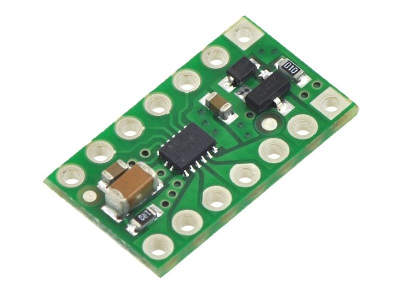
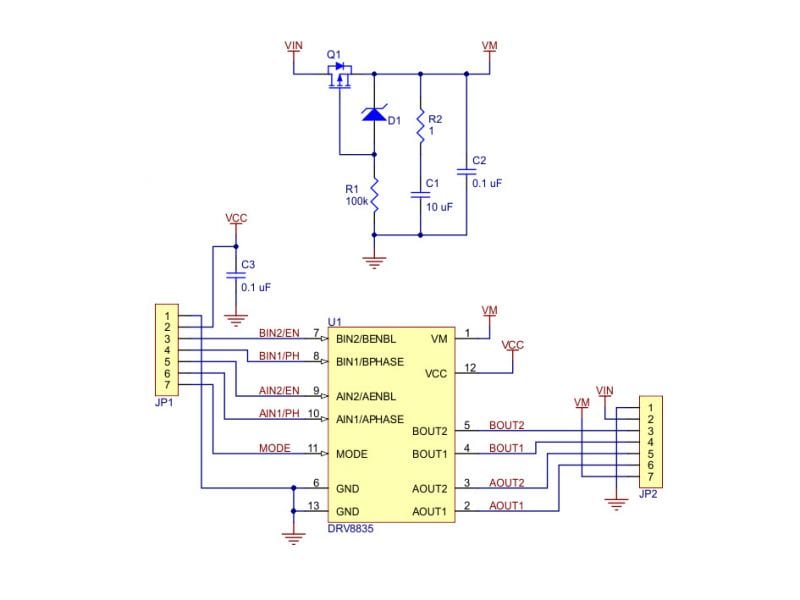
Texas Instruments’ DRV8835 is a tiny dual H-bridge motor driver IC that can be used for bidirectional control of two brushed DC motors at 0 V to 11 V. It can supply up to about 1.2 A per channel continuously and can tolerate peak currents up to 1.5 A per channel for a few seconds, making it an ideal driver for small motors that run on relatively low voltages. The DRV8835 is a great IC, but its small, leadless package makes it difficult for the typical student or hobbyist to use; our breakout board gives this driver the form factor of a 14-pin DIP package, which makes it easy to use with standard solderless breadboards and 0.1″ perfboards. Since this board is a carrier for the DRV8835, we recommend careful reading of the DRV8835 datasheet. The board ships populated with SMD components, including the DRV8835, and adds a FET for reverse battery protection.
Two 1×7-pin breakaway 0.1″ male headers are included with the DRV8835 dual motor driver carrier, which can be soldered in to use the driver with breadboards, perfboards, or 0.1″ female connectors. (The headers might ship as a single 1×14 piece that can be broken in half.) The right picture above shows the two possible board orientations when used with these header pins (parts visible or silkscreen visible). You can also solder your motor leads and other connections directly to the board.
Motor and motor power connections are made on one side of the board and logic power and control connections are made on the other. The driver requires a motor voltage between 0 V and 11 V to be supplied to the VIN or VMM pin and a logic voltage between 1.8 V and 7 V to be supplied to the VCC pin; the logic voltage can typically be supplied by or shared with the controlling device. The VIN pin is the reverse-protected motor supply input and is the recommended point for connecting motor power. However, driver performance will start getting worse when the input voltage to the reverse-protection circuit is below a few volts, and 1.5 V is the lower limit of where the VIN pin can be used. For very low voltage applications, the motor supply should be connected directly to VMM, which bypasses the reverse-protection circuit.
The DRV8835 features two possible control modes: IN/IN and PHASE/ENABLE. The MODE pin determines the control interface. Each control input is pulled low through a weak pull-down resistor (approximately 100 kΩ), so the driver will be in the IN/IN mode if the MODE pin is left disconnected, and the driver outputs will be disabled by default. Setting the MODE pin high, either with a pull-up resistor or a driving-high I/O line, sets the driver to PHASE/ENABLE mode, where the PHASE pin determines the motor direction and the ENABLE pin can be supplied with a PWM signal to control the motor speed. This mode is generally easier to use as it only requires one PWM per channel, but it only allows for drive/brake operation. (Drive/brake operation usually provides a more linear relationship between PWM duty cycle and motor speed than drive/coast operation, and we generally recommend using drive/brake operation when possible.)
Only logged in customers who have purchased this product may leave a review.

Reviews
There are no reviews yet.