With the holidays fast approaching we would like to announce our holiday schedule which is outlined below: At Solarbotics: Monday, December 24th to Wednesday, December 26th - Offices Closed December 27th, 28th, 31st - Open, regular hours Tuesday, January 1 - Offices Closed Wednesday, January 2 - Open, back to regular hours At ActiveTech Calgary:
Solarbotics Raspberry Pi 3 SAFE Assembly...
Dave Hrynkiw
April 25, 2016
The instructions for assembling the Pi v3 and the previous acrylic Pi SAFE are quite similar. The only difference between the models is the location of the LED light pipes, so these Pi3 instructions apply generally to all Pi SAFE versions.
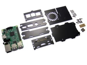
1. Your Parts!

- 8 x 4-40 nuts
- 8 x 4-40 x 3/8" bolts
- 2 x Clear acrylic light-pipes
- 4 x Black acrylic spacers
- 6 x Black acrylic SAFE sides (shown here with brown protective paper already removed)
- 0 x Raspberry Pi (sorry - not included in the kit!)
2. The Baseplate

Find 4 of the 4-40 x 3/8" bolts, and put them through the baseplate, and press the spacers on from the other side. Thee bolts will sort of stay put until you can get the Raspberry Pi on the baseplate. (If adding to a VESA mount, do only 2 diagonal screws)
3. Adding the Raspberry Pi

Slide the Raspberry Pi onto the bolts. The Pi is designed for metric M3 hardware, but we're still using imperial #4 hardware, which is a smidge bigger. The bolts may need to be screwed through the holes in the Pi.
Add the #4 nuts, and tighten them down.
4. Adding 3 of the 4 Sides

Arrange the sides as shows. The sideplate on the top in this image has the long cutout to accommodate a ribbon cable from the 40-pin expansion port. The front faceplate on the right (with the label engravings face-down) is for the communications side. The sideplate on the bottom has the ports for the power, video, and audio I/O.
Align them all up on the baseplate, and use a pair of 4-40 nuts and bolts to lock them in place.
5. Adding the SD-Card / LightPipe Faceplate

Lay the final side faceplate face-down beside the assembly, and pop the clear lightpipe parts out of their holder. It is not necessary to strip the paper off this part.
Sandwich the two lightpipes together, and push them into the lightpipe indicator hole. They will sit a bit loose until the faceplate is attached to the baseplate.

Carefully assemble this assembly to the baseplate, and finish attaching it with the remaining 4-40 nuts and bolts.
Step 6: Top Plate mounting
Notch the top plate into the slots in the rear faceplate, and gently flex the frontplate out to let the tab snap into place. You're ready to power up, with full access to the indication LEDs on the Pi mainboard via the lightpipes!

.
MORE POSTS
Push Pogo Pins back in stock.
For all of you who have been patiently waiting for new stock on our Push Pogo Pins, here they are! Unfortunately, we couldn't get any more PP2 or PP6 style. Additionally, this new inventory has caused us to slightly raise the price to $0.60USD & $0.90CDN (4+ pricing).
Ex-Interns and their projects...
Jerome Demers, our ex-intern of two seasons, just sent me a link to one of his latest projects. The (sigh...) "Fart-o-Meter". He even put it up on Instructables too. Good to see the experience he got at Solarbotics is being put to good use...
More new stuff?
What's going on here? We haven't had this much new product come online so quickly since... since... well, let's just say "in quite a while!" Here's a book to add to your bookshelf: "Building Robot Drive Trains" by Clark & Owings. It's an excellent text on anything you need to know about putting power & […]

Solarbotics has been operating for more than 25 years, bringing electronics know-how and supplies to both the electronics professional and hobbyist. We'll be happy to help you too!
Solarbotics, Ltd. is not responsible for misprints or errors on product prices or information. For more information, please see our Terms and Conditions.
Warning: This product contains chemicals known to the State of California to cause cancer and birth defects or other reproductive harm.
Please visit www.P65Warnings.ca.gov for more information. This item was manufactured prior to August 31, 2018.