


We are back, ready to take your orders. Not only are we back but we are ready for a new year with many things to serve you better. We have brought back the SCPD solar cells. Future enhancements and improvements in the online web ordering. Expect future enhancements such as more videos, more data on […]
BEP Application: Bare Bones PhotoVore
Solar botics
July 11, 2007
 |
We like to have some play time at Solarbotics, and the "Bare Bones Photovore" is the results of one of these play sessions. It's a very simple (amongst the simplest, we'll hazard to say) light-seeking solar-powered robot, and find it easy to build using the Bicore Experimenter's PCB.New Development: We've just discovered that we've reinvented the wheel! Original kudos to Math Vos, on his "LightHead 2" (here's the circuit) which he developed (when? No idea...) to make a very simple headbot. Andy Pang even did a tutorial on how to do it! Well, at least we were first to put it into a photovore... |
So How do it Work?
The operation of this device is very simple, so simple in fact that it need not be explained!
*whap*
...or maybe it'd be a good idea anyways...
Eyes: A voltage divider is created using two reverse biased photodiodes. Why reverse biased? If they are forward biased, they would short out the power supply and that usually ends up being a bad thing. Basically a reverse biased photodiode acts like a photoresistor, meaning that the resistance varies with light intensity. The voltage at the center of the voltage divider will vary with changes in light level.
Brains: The voltage divider output is fed into the input of an inverter, specifically a 74AC240 inverter. These inverters have the property of switching at close to 1/2 +Vcc (1/2 the power supply voltage). This combined with the tight tolerances of photodiodes usually make tuning unnecessary.
Brawn: This signal coming from the outputs of the 74AC240 gate is inverted so that either one or the other motor is moving, but not both at the same time. Depending on how the motors are arranged it can either be running towards or away from light. It can also spin on the spot if one motor is connected backwards, which is amusing, but ultimately useless, so why bother?
Solar Engine
Basically, what a solar engine does is store the power from a solar cell in a storage capacitor. When the charge voltage reaches a certain level it is dumped to the load, in this case being the motors. The solar engine would be unnecessary if the solar cell could power the robot directly but this would seriously limit the lighting conditions it could run in, not to mention the size of the solar cell needed.
We opted to go with the efficient and versatile Miller Solar Engine (MSE). The MSE works by switching the ground line of the load circuit through a transistor. When the transistor is off, the storage capacitor is separated from the rest of the circuit so the the capacitor can get charged by the solarcell.
Optional Tactile sensors
The tactile sensors are a bit of a kludge as they basically force the voltage divider high or low. The problem arises that if both sensors are triggered at the same time, they will cause a short circuit. This problem is avoided by putting a series resistor with one of the tactiles, a simple 1K resistor seems to do the job.
Circuit Diagram: |
Wiring Diagram: |
Here's a collection of the circuit diagrams in a nice, high-quality 31k PDF
Assembly procedure:
 |
1. Collect all your parts:Or click this link to add them to your cart.Parts list: 1 - MD2 BEP board Solar Engine: 1 - 1N914 diodes Tactile sensors: 1 - 1K resistor
|
  |
2. Soldering components on the BEPLets solder components into the BEPs. Start with the 74AC240, and mount it into the MD2 board. Please take care to solder it in the right way, as these are a pain to desolder. With the MSE1.0, the 1381 value is "G". The transistor is a 2N2222 and the C2 value is 0.47µF. We'll deal with the C1 later. Power is routed to the 25c BB1 board via two jumper wires, which also act as anchors to the MD2 PCB. Try to angle the 25c BB1 board at a 45 degree angle. |
 |
3. Solder bridges on the MD2There are four solder bridges that need to be made on the MD2. Group the input pads into two sets, and the output pads by flowing solder over these sets of pads. The purpose of this is to supply more drive current to the motors as well as keeping any free gates from floating. |
 |
4. Add the C1 3300µF cap to the SolarengineHere the '+' side of the 3300µF cap is soldered into the '+' rail of the MSE PCB. For convenience, the '-' side of the capacitor is soldered to the diode's cathode (the side with the stripe). |
 |
5. Power jumper to SolarengineAs each of the BEP pcbs have a ground trace running around the edge of the board, it's an easy task to join the ground of each board together. Just flow some solder from the edge of one PCB to the other. The Vcc (+) needs to be wired with a jumper to the MD2 board so they both share a common Vcc. |
 |
6. Front skidTo make a skid point for the nose of your robot, take a paperclip and snip off one of the elbowed lengths. Solder the round part of the paperclip to the angled 25c BB1. This solution isn't very fancy, but it is cheap, light and should last a long time provided its not running on sandpaper. You did get rid of that sandpaper flooring in favour of hardwood, right? |
    |
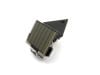
6. Adding the motorsA couple short lengths of paperclip were soldered directly to the motor, then soldered to the MD2 board. The motors are angled downward at approximately 45 degrees. The side profile of the photovore shows that it is quite "flat". Since the motors are angled downward, it helps reduce drag if the motors point in a parallel direction, which means they're not twisted inwards or outwards - just in line with the side edge of the PCB. Once you are satisfied with the angle the motors are set at, solder in a cross brace to make the motor mount more rigid. |
  |
7. The eyesSolder a pair of photodiodes into the front 25c BB1 board. It's not critical which pads you choose, just as long as they're facing frontward and outward. Shown here are the eye connections. The white wire is the center connection between the eyes (from anode to cathode). The lower left connection is to the outside ground rail so this is the anode of the photodiode (long lead). To the bottom right is a connection from the cathode of the other photodiode to the +Vcc rail running down the center of the 25c BB1 board. |
 |
8. Output to input crossThe green wire here shows the connection between the output of a group of inverters to the input of the other inverters. What this does is ensures that the outputs will always be complementary to each other, when one output is high then the other output is low. |
 |
9. Voltage dividerThe blue wire shown here connects the center of the voltage divider to the inverter input. This is the group of MD2 inputs that the green wire was not connected to. |
 |
10. Motor wiresThe motor polarity shown here is correct and will move the photovore forward and towards the light. The connections of the motor between the outputs of the MD2 to ground. If a motor is running backwards, correct it by simply reversing the motor connections. |
  |
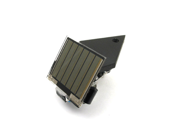
11. Adding the solar cellSticky tape the solarcell. Or use glue. Chewing gum? Road tar! You decide. This close-up of the solar cell connections shows the positive from the solar cell can go to any '+' on any board as this is a common connection. The negative solar cell connection must connect to the '-' solar cell input, which connects the solar cell in parallel with the 3300µF storage capacitor. |
 |
12. Done!.. sort of...Finishing this step means you have a solar powered bug that seeks light but is ill-equipped to avoid running into things. It needs some tactile sensors. At this point, we've added some hobby-store silicone tubing to the motor output shafts for better traction and quieter operation. |
   |
13. Adding the tactile sensorsThe pins shown here are soldered to the center of the voltage divider. The spring to the left is soldered to a free pad and the spring to the right is soldered to the nearest ground rail. Underneath a 1K resistor is soldered from the +Vcc rail to the free sensor spring. The idea here is that one tactile will connect the voltage divider to ground, and the other tactile will tie the voltage divider to +Vcc. The resistor prevents a short when both sensors are triggered. |
|
14. Finished!Done and done. |
Troubleshooting:
-
Troubleshooting? What could possible go wrong with such a simple design? Tch, tch...
-
If the motors don't move at all the problem is most likely with the solarengine, so concentrate your search there. If the solar engine seems to work fine then check that you actually jumpered the MSE '+' connection to the MD2 board.
-
If the motors move but the light falling on the eyes doesn't seem to affect which motor fires then check the voltage divider. The connection from the voltage divider may be going to the wrong set of inputs.
-
Another problem may be the solder bridges, check for any shorts that aren't supposed to be there.
Other Musings and Hints:
-
This device has the ability to run under solar or battery power, all that's needed for battery power is a switch and a battery.
-
As with all devices using the 74XX240 don't try running it with a 9V battery, the chip can't handle the voltage and will most likely turn into magic smoke right before your eyes. Keep the voltage below 6 volts!
-
Hey! If you turf the other motor, and wire up a single motor between the outputs, you get the "Bare Bones Photo Head"! This one uses a VPM motor for seemingly-invisible motion:

-
An older Shok popper, similar in size and performance but with a few extra parts.

Copyright © Solarbotics Ltd., 2003, all rights reserved.
MORE POSTS
Project: Experiments in Watermelon Filam...
It takes a while to get to know all the quirks of your 3D printer and filament well. We thought we'd add to the knowledge base and share what we've learned about using the eSun 1.75mm PLA filament in Glass Watermelon Red on our Kossel Pro delta style 3D printer.
Server Issue Update
EDIT: Our wizards were successful and everything should be displaying properly now! Hi everyone, we've noticed that our website is having trouble with displaying images. We have our IT wizards working on it right now and should be back up and running like normal shortly! If you have any questions or concerns please email us […]
Project Monday: All-Seeing Eye
This week's project is coming to you fresh from Alex, an engineer in our R&D department, with some help from Yana, our graphic designer. They've developed an enclosure based on the SAFE that accommodates sensor mounts on each side in addition to an Arduino-style board within. And after putting on some short range and long […]
Solarbotics has been operating for more than 25 years, bringing electronics know-how and supplies to both the electronics professional and hobbyist. We'll be happy to help you too!
Solarbotics, Ltd. is not responsible for misprints or errors on product prices or information. For more information, please see our Terms and Conditions.
Warning: This product contains chemicals known to the State of California to cause cancer and birth defects or other reproductive harm.
Please visit www.P65Warnings.ca.gov for more information. This item was manufactured prior to August 31, 2018.